
Datasheet for IXYS IXGA12N60C and IXGP12N60C IGBTs showing electrical, thermal and mechanical specifications.
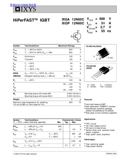
The IXYS IXGA12N60C and IXGP12N60C are high‑frequency insulated‑gate bipolar transistors offered in TO‑263 AA and TO‑220 AB packages. The document provides test conditions, maximum ratings, characteristic curves and mechanical dimensions.
Key specifications include a 600 V collector‑emitter rating, ±20 V gate‑emitter rating, and detailed switching and thermal performance data for use in PFC circuits, motor drives and high‑power audio amplifiers.
| Maximum collector‑emitter voltage (VCE) | 600 V |
|---|---|
| Maximum gate‑emitter voltage (continuous) | ±20 V |
| Maximum gate‑emitter voltage (transient) | ±30 V |
| Maximum collector current at 25 °C (IC25) | 4 A |
| Maximum collector current at 90 °C (IC90) | 2 A |
| Turn‑on delay (td(on)) | 20 ns |
| Turn‑off delay (td(off)) | 60 ns |
| Junction‑to‑case thermal resistance (RthJC) | 1.25 K/W |
The IGBT is rated for a maximum collector‑emitter voltage of 600 V.
The turn‑on delay (td(on)) is specified as 20 ns.
The junction‑to‑case thermal resistance (RthJC) is 1.25 K/W.