
This datasheet lists the pin functions and pinout of the PS8501.
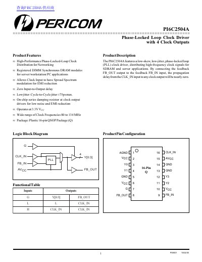
The Pericom PI6C2504A is a high-performance Phase-Locked-Loop (PLL) clock driver designed for networking, Registered DIMM Synchronous DRAM modules, and server/workstation/PC applications. It features a low-skew, low-jitter design with a maximum cycle-to-cycle jitter of 75ps and allows for spread spectrum modulation on the clock input to reduce EMI.
The device operates at a 3.3V supply voltage and supports a wide range of clock frequencies from 80 to 134 MHz. It is packaged in a 16-pin QSOP package and includes on-chip series damping resistors at the clock outputs to minimize noise and EMI.
| Clock Frequency | 80 to 134 MHz |
|---|---|
| Operating Temperature | 0 to 70 °C |
| Package Type | 16-pin QSOP |
| Cycle-to-Cycle Jitter | 75ps max |
| Max Power Dissipation | 1.0 W |
The maximum cycle-to-cycle jitter is 75ps.
Yes, the CLK_IN allows spread spectrum clock input for EMI reduction.
The stabilization time after power up is 1 ms.