
The CDC924 is a clock synthesizer/driver for PC motherboards that supports Pentium III class motherboards. It uses a 14.318 MHz crystal input to generate multiple output frequencies. The CDC924 includes spread spectrum clocking (SSC) with 0.5% downspread for reduced electromagnetic interference (EMI) performance. It also features power management control terminals, low output skew and jitter for clock distribution, and supports 2.5 V and 3.3 V supplies. The CDC924 generates various clocks including CPU, PCI, APIC, and REF clock signals.
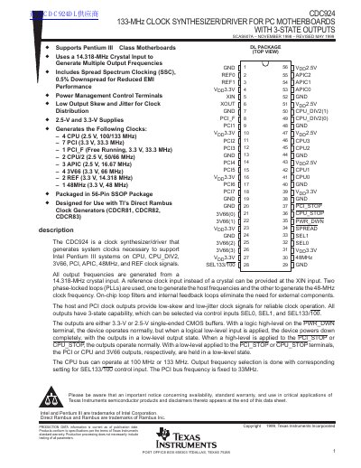
The CDC924 is a clock synthesizer and driver designed to support Intel Pentium III class motherboards. It uses a 14.318-MHz crystal input to generate various system clocks, including CPU, PCI, APIC, and reference signals. The device incorporates two phase-locked loops (PLLs) and on-chip loop filters to eliminate the need for external components.
| Supply Voltage VDD (3.3V) | 3.135 – 3.465 V |
|---|---|
| Supply Voltage VDD (2.5V) | 2.375 – 2.625 V |
| Crystal Frequency f(XTAL) | 14.318 MHz |
| Operating Temperature Range | -0 °C to 85°C |
| Package Type | 56-Pin SSOP Package |
The device uses a 14.318-MHz crystal input to generate multiple output frequencies.
No, on-chip loop filters and internal feedback loops eliminate the need for external components.
The device powers down completely, with all outputs forced into a low-level output state.