
The MC10E/100E431 is a 3-bit flip-flop with differential clock, data input and data output. The asynchronous Set and Reset controls are edge-triggered rather than level controlled. This allows the user to rapidly set or reset the flip-flop and then continue clocking at the next clock edge, without the necessity of de-asserting the set/reset signal (as would be the case with a level controlled set/reset). The E431 is also designed with larger internal swings, an approach intended to minimize the time spent crossing the threshold region and thus reduce the metastability susceptibility window. The differential input structures are clamped so that the inputs of unused registers can be left open without upsetting the bias network of the device. The clamping action will assert the D and the CLK sides of the inputs. Because of the edge triggered flip-flop nature of the device simultaneously opening both the clock and data inputs will result in an output which reaches an unidentified but valid state. Note that the input clamps only operate when both inputs fall to 2.5V below VCC.
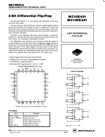
This document is a technical datasheet for the Motorola MC10E431 and MC100E431, which are 3-bit differential flip-flops featuring differential clock, data input, and data output. The devices utilize edge-triggered asynchronous Set and Reset controls to allow rapid setting or resetting without de-asserting signals.
The datasheet provides comprehensive electrical specifications, including DC and AC characteristics such as maximum toggle frequency (1100 MHz minimum), propagation delays, and setup/hold times across temperature ranges. It also includes a pinout diagram for the 28-lead PLCC package and a logic diagram illustrating the internal structure.
| Maximum Toggle Frequency | 1100 MHz Min. |
|---|---|
| Package Type | 28-Lead PLCC |
| Operating Temperature Range | -40°C to 85°C |
| Vee Reference Output Voltage (10E) | -1.43V to 1.30V |
| Vee Reference Output Voltage (100E) | -1.38V to 1.26V |
| Minimum Input Swing | 150 mV |
The minimum toggle frequency is 1100 MHz.
No, the asynchronous Set and Reset controls are edge-triggered rather than level controlled.
The device uses a 28-Lead PLCC package.