
The MC10E/100E431 is a 3-bit edge-triggered flip-flop. The device has 3 data input pins, 3 data output pins, 1 clock input pin, 1 data set input pin, and 1 data reset input pin. The clock and data inputs are differential. This allows the device to have a larger swing and faster switching speed. The device also has input clamp functions to prevent the device from generating bias voltages when it is not in use. When the data or clock inputs are short-circuited, the device will output a determined state.
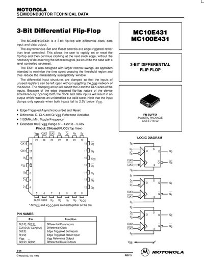
The document describes the MC10E431 and MC100E431 as 3-bit differential flip-flops featuring differential clock, data input, and data output. The device utilizes edge-triggered asynchronous Set and Reset controls to allow rapid setting or resetting without de-asserting signals between clock edges.
| Min. Toggle Frequency | 1100 MHz |
|---|---|
| Package Type | 28-Lead PLCC |
| Max Toggle Frequency (-40°C) | 1000 MHz |
The device has a minimum toggle frequency of 1100 MHz.
No, they are edge-triggered rather than level controlled.