
This product is the MC10E/100E155 chip data sheet, which introduces the function characteristics, pin definition, logic diagram and other information of the chip.
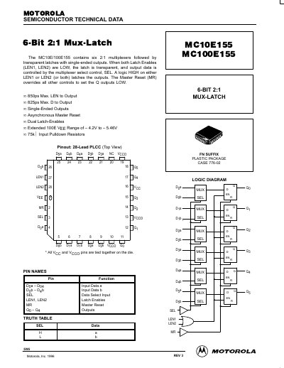
This document is a technical datasheet for the Motorola MC10E155 and MC100E155 integrated circuits. These devices contain six 2:1 multiplexers followed by transparent latches with single-ended outputs. The datasheet provides a logic diagram, pinout description for the 28-lead PLCC package, and a truth table explaining the operation of the Latch Enables (LEN), Select (SEL), and Master Reset (MR) inputs.
| Package Type | 28-Lead PLCC |
|---|---|
| Max LEN to Output MUX-Latch | 850ps |
| Max D to Output | 825ps |
| Input Pulldown Resistors | 75kQ |
| VEE Range (100E) | -4.2V to -5.46V |
When both Latch Enables (LEN1, LEN2) are LOW, the latch is transparent, and output data is controlled by the multiplexer select control, SEL.
The Master Reset (MR) overrides all other controls to set the Q outputs LOW.