
This document is an applications note for BGA430 and BGB540 MMIC, introducing their application in European, Asian and North American DBS LNB I.F. amplifier chains
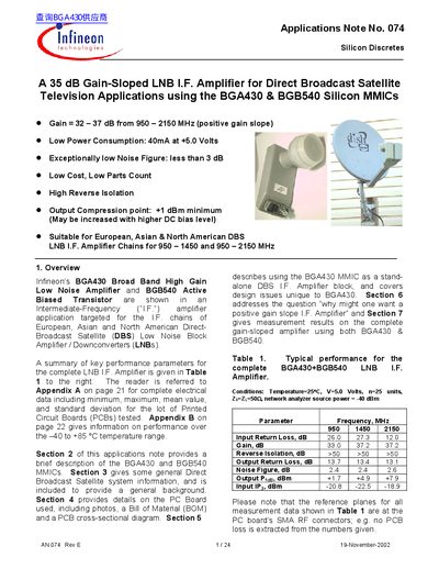
This document is an Applications Note (No. 074) detailing the use of Infineon's BGA430 Broad Band High Gain Low Noise Amplifier and BGB540 Active Biased Transistor in Intermediate-Frequency (I.F.) amplifier chains for Direct-Broadcast Satellite (DBS) Low Noise Block Amplifiers/Downconverters (LNBs). The note covers applications for European, Asian, and North American DBS systems operating at 950–2150 MHz.
The document provides a summary of key performance parameters for the complete LNB I.F. amplifier, including typical gain, noise figure, and isolation values across different frequencies. It describes the specific features of the BGA430 (a three-stage MMIC) and the BGB540 (an active-biased RF transistor), explains general DBS system information, and includes details on a reference Printed Circuit Board (PCB) used for testing.
| Gain (950-2150 MHz) | 32 — 37 dB |
|---|---|
| Power Consumption | 40mA at +5.0 Volts |
| Noise Figure | less than 3 dB |
| Output Compression point | +1 dBm minimum |
The amplifier is suitable for European, Asian & North American DBS LNB I.F. Amplifier Chains for 950 — 1450 and 950 — 2150 MHz.
The BGA430 only requires three external elements: input / output DC blocking capacitors, and a single decoupling capacitor on the power supply pin.