
This datasheet provides the data information of IR2153(S) half-bridge gate driver, including product features, typical connections, package dimensions, etc.
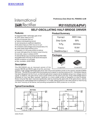
The document is a preliminary data sheet for the IR2153(D)(S) & (PbF), an integrated 600V half-bridge gate driver. It describes features such as true micropower startup, tighter initial deadtime control, and improved noise immunity compared to previous ICs like the IR2155.
The text includes absolute maximum ratings, recommended operating conditions, and typical component values for timing resistors and capacitors. Detailed electrical characteristics are provided for low voltage supply, floating supply, oscillator, and gate driver output parameters.
| Integrated half-bridge gate driver voltage | 600V max. |
|---|---|
| Zener clamp voltage (typical) | 15.6V |
The absolute maximum rating for the high side floating supply voltage (VB) is 625 V.
The typical output deadtime between HO or LO signals is 1.2 microseconds.
The device can operate with a maximum junction temperature of 125 C.