
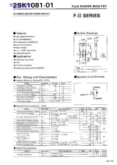
This datasheet describes the 2SK1081-01 N‑channel silicon power MOSFET from Fuji Power. It lists key features such as high‑speed switching, low on‑resistance, avalanche‑proof design, and a maximum drain‑source voltage of 800 V.
The document includes absolute maximum ratings, detailed electrical and thermal characteristics, and typical output, transfer, and capacitance curves. It also provides graphs of on‑state resistance versus temperature and gate‑threshold voltage versus temperature, useful for designers selecting the device for switching regulators, DC‑DC converters, and power amplifiers.
| Drain‑source voltage (VDS) | 800 V |
|---|---|
| Pulsed drain current (ID(pulse)) | 21 A |
| On‑state resistance (RDS(on)) typical | 2.2 mΩ |
| Input capacitance (CISS) typical | 1800 pF |
| Output capacitance (COSS) typical | 210 pF |
The device is rated for a maximum drain‑source voltage of 800 V.
The typical on‑state resistance is 2.2 mΩ.
Typical input capacitance is 1800 pF and output capacitance is 210 pF.