
The SY10/100E160 are high-speed, 12-bit parity generator/checkers with differential outputs, for use in new, high-performance ECL systems. The output Q takes on a logic HIGH value only when an odd number of inputs are at a logic HIGH. A logic HIGH on the enable input (EN) forces the output Q to a logic LOW. An additional feature of the E160 is the output register. Two multiplexers and their associated signals control the register input by providing the option of holding present data, loading the new parity data or shifting external data in. To hold the present data, the Hold signal (HOLD) must be at a logic LOW level. If the HOLD signal is at a logic HIGH, the data present at the Q output is passed through the first multiplexer. Taking the Shift signal (SHIFT) to a logic HIGH will shift the data at the S-IN pin into the output register. If the SHIFT signal is at a logic LOW, the output of the first multiplexer is then passed through to the register. The register itself is clocked on the rising edge of CLK1 or CLK2 (or both).
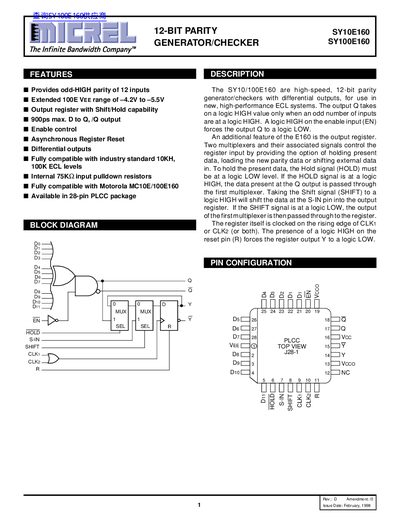
The SY10E160 and SY100E160 are high‑speed 12‑bit parity generator/checker devices designed for ECL systems. They provide odd‑HIGH parity of 12 inputs, feature an output register with shift/hold capability, and include enable control and asynchronous reset. The devices are compatible with standard 10K/100K ECL levels and Motorola MC10E/100E160 parts.
The ICs are supplied in a 28‑lead PLCC package and include pin functions such as data inputs, serial data input, enable, hold, shift, clock inputs and reset. Electrical specifications cover both DC and AC characteristics, including propagation delays (400‑950 ps) and supply currents (typical 82 mA). Mechanical drawings show package dimensions and lead layout.
| Parity type | odd‑HIGH |
|---|---|
| Input voltage range (VEE) | -4.2 V to -5.5 V |
| Package | 28‑lead PLCC (J28‑1) |
The output Q is logic HIGH only when an odd number of the 12 inputs are logic HIGH.
A logic HIGH on the enable input forces the output Q to a logic LOW.
The devices are fully compatible with industry‑standard 10 kΩ and 100 kΩ ECL levels.