
PROFET® ITS 716G is a Smart High-Side Power Switch For Industrial Applications product from Infineon, featuring four 40V/140mΩ status feedback channels, and is used in industrial applications with a load voltage of 12V/24V.
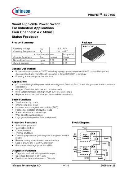
The PROFET® ITS 716G is a smart high‑side power switch designed for industrial applications. It integrates four independent channels, each with a typical on‑state resistance of 140 mΩ and a nominal load current of up to 2.6 A (5.3 A when all four channels are active). The device operates from 5.5 V to 40 V and includes a range of built‑in protection functions.
The datasheet provides detailed pin definitions, maximum ratings, thermal and electrical characteristics, as well as truth tables and timing diagrams. Ordering information and package dimensions are listed at the end of the document.
| Operating voltage (Vob) | 5.5 V – 40 V |
|---|---|
| On‑state resistance (Ron) | 140 mΩ (typical) |
| Nominal load current (single channel) | 2.6 A |
| Current limitation (I_lusen) | 6.5 A |
| Supply voltage for full short‑circuit protection | 36 V |
| Maximum supply voltage (overvoltage protection) | 43 V |
| Operating temperature range (Ta) | -30 °C … +85 °C |
| Turn‑on time (t_on) | 100 µs – 250 µs |
| Turn‑off time (t_off) | 100 µs – 270 µs |
The device operates from 5.5 V up to 40 V.
It provides four independent high‑side channels.
Each channel has a typical on‑state resistance of 140 mΩ.