
PM100RL1A060 is a three-phase 100A, 600V intelligent power module that uses the latest fifth-generation full-gate CSTBTTM chip. It has an integrated drive and protection logic circuit, detects short-circuit, over-temperature and under-voltage, and has UL certification
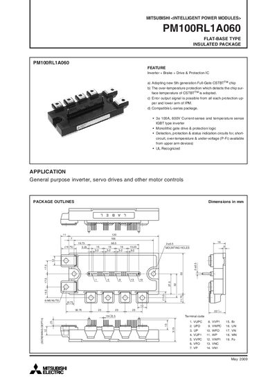
This document describes the Mitsubishi Electric PM100RL1A060 Intelligent Power Module, a flat‑base insulated package that integrates an inverter, brake, drive and protection ICs. It outlines the module’s features, such as the 5th‑generation Full‑Gate CSTBT™ chip, over‑temperature protection, and compatibility with L‑series packages, and lists typical applications like general‑purpose inverters, servo drives and motor controls.
The datasheet includes detailed electrical and mechanical ratings, thermal characteristics, recommended mounting torque, and testing procedures. It also provides performance curves, switching loss data, and transient thermal impedance information to aid designers in PCB layout, component selection, and safe operation of the module.
| Continuous Collector Current (Ic) | 100 A |
|---|---|
| Peak Collector Current (IcP) | 200 A |
| Power Dissipation (Pc) | 390 W |
| Junction Temperature Range | -20 °C to +150 °C |
| Brake Part Continuous Current | 50 A |
| Brake Part Power Dissipation | 284 W |
| Weight | 380 g |
| Supply Voltage (VD) | 13.5 V – 16.5 V |
The inverter part is rated for a continuous collector current of 100 A.
Minimize wiring length between the opto‑coupler and the IPM input terminals, keep stray capacitance low, and place a low‑impedance capacitor between VCC and GND of each fast‑switching opto‑coupler.
The over‑temperature protection trips at 135 °C.