
This document describes the features and usage of the CME-PD01 communication module.
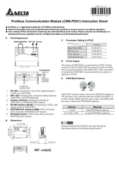
The manual describes the panel layout of the CME-PD01, including LEDs that indicate connection status, address switches for setting the PROFIBUS address, and the RS‑485 and PROFIBUS‑DP interfaces. It also lists the physical dimensions of the module and the wiring requirements for power and communication.
Additional sections cover VFD‑E parameter settings (baud rate, RTU format), power supply details (the module is powered from the VFD‑E via the supplied RJ‑45 cable), and how to configure the PROFIBUS address using the ADDH and ADDL rotary switches.
| Baud Rate | 9600 |
|---|---|
| Communication Format | RTU 8N2 |
| Power Supply Source | Supplied from VFD‑E via RJ‑45 cable |
Use the two rotary switches ADDH and ADDL; ADDH sets the upper 4 bits and ADDL sets the lower 4 bits of the address in hexadecimal.
The SP LED shows the connection status between the VFD‑E and the CME‑PD01, while the NET LED shows the connection status between the CME‑PD01 and the PROFIBUS‑DP network.
The module receives power from the VFD‑E through the RJ‑45 cable that is supplied with the unit.