
This document introduces the features and characteristics of DELTA VFDB 4132 series brake modules.
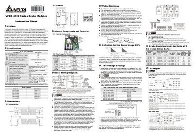
The VFDB 4132 series brake modules are used with Delta AC motor drives to absorb regeneration energy during motor deceleration. The modules dissipate this energy in dedicated brake resistors and must be installed with BR series brake resistors for optimal performance.
The document provides detailed specifications, wiring guidelines, voltage setting tables, jumper configuration for master/slave operation, and safety warnings such as overheat alarm activation and required grounding. It also includes dimensions and a list of compatible brake resistors.
| Continuous Discharge Current | 75 A |
|---|---|
| DC Voltage Rating | 480‑750 VDC |
| Operating Temperature Range | -10 °C to +50 °C |
| Overheat Alarm Activation Temperature | Above 95 °C |
Use 4~6 AWG wire for the DC+ and DC‑ power input terminals.
The alarm activates when the heat‑sink temperature exceeds 95 °C.
Ensure all power is turned off before proceeding with any wiring or jumper adjustments.