
Technical note describing the Philips 2656 CP1002 System Memory Interface, its memory map, I/O pins, and the PIPBUG2 and PIPLA firmware.
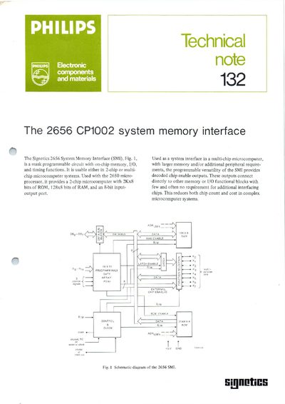
The Philips 2656 CP1002 System Memory Interface (SMI) is a mask‑programmable gate array that provides 2 K×8 bits of ROM, 128×8 bits of RAM and an 8‑bit I/O port for use with the Signetics 2650 microprocessor. The device includes two firmware packages—PIPBUG2, a loader/debug monitor, and PIPLA, an on‑board assembler—pre‑programmed into the ROM.
The note details the memory allocation, I/O pin functions, command set for PIPBUG2, and required board modifications (e.g., to the ABC1500) to integrate the SMI. It also explains how to set breakpoints, use subroutines, and program the device via terminal commands.
| ROM size | 2 K×8 bits |
|---|---|
| RAM size | 128×8 bits |
| I/O port width | 8‑bit |
| ROM address range | H'0000'–H'07FF' |
| RAM address range | H'0800'–H'087F' |
| Firmware packages | 2 (PIPBUG2, PIPLA) |
| PIPBUG2 program location | H'0000'–H'03FF' |
| PIPLA program location | H'0400'–H'07FF' |
The device contains two firmware packages: PIPBUG2, a loader/debug monitor, and PIPLA, an assembler that generates object code in memory.
PIPBUG2 allows two breakpoints to be set.
Only pins XO and X7 provide I/O port functions; the other pins can be used for chip‑enable or temporary storage.