
The CDC2510 is a high-performance, low-skew, low-jitter, phase-lock loop (PLL) clock driver. It uses a PLL to precisely align, in both frequency and phase, the feedback (FBOUT) output to the clock (CLK) input signal. It is specifically designed for use with synchronous DRAMs. The CDC2510 operates at 3.3-V VCC and provides integrated series-damping resistors that make it ideal for driving point-to-point loads. One bank of ten outputs provide ten low-skew, low-jitter copies of CLK. Output signal duty cycles are adjusted to 50 percent, independent of the duty cycle at CLK. All outputs can be enabled or disabled via a single output enable input. When the G input is high, the outputs switch in phase and frequency with CLK; when the G input is low, the outputs are disabled to the logic-low state. Unlike many products containing PLLs, the CDC2510 does not require external RC networks. The loop filter for the PLL is included on-chip, minimizing
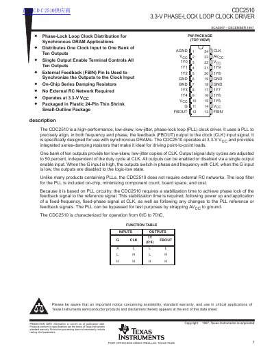
The CDC2510 is a high-performance, low-skew, low-jitter phase-lock loop (PLL) clock driver specifically designed for use with synchronous DRAMs. It distributes one clock input to ten outputs and includes an on-chip series-damping resistor network, eliminating the need for external RC networks.
| Supply Voltage | 3.0 V to 3.6 V |
|---|---|
| Operating Temperature Range | 0°C to 70°C |
| Clock Frequency Range | 25 MHz to 125 MHz |
| Number of Outputs | 10 |
No, it does not require external RC networks because the loop filter is included on-chip.
The stabilization time required to achieve phase lock is 7 ms.