
The Power MOSFET is a very popular switching device used in switching power supplies and DC-DC converters. Their operation frequency is being continuously increased to reduce size and increase power density. This causes high di/dt, intensifies the negative effect from parasitic inductances, and results in high voltage spike between the Power MOSFET drain and source during device turn off. The spike is worst at power on due to empty bulk capacitors and small inductance because the transformer primary side inductance almost reaches the level of leakage inductance. Fortunately, the Power MOSFET is equipped to withstand a certain level of stress, unnecessitating expensive protection circuits. This note presents an effective way to determine the applicability of a Power MOSFET in an application. The designers can balance between cost and reliability.
The document introduces a rating system to determine the feasibility of Power MOSFETs in applications involving high di/dt and parasitic inductances, which cause voltage spikes during device turn-off. It explains how to use Single Pulse UIS Safe Operating Area (SOA) graphs to balance cost and reliability without needing expensive protection circuits.
The note details methods for analyzing over-voltage conditions, distinguishing between non-avalanche breakdowns and avalanche modes. It provides formulas and procedures for calculating junction temperature during transient power pulses and repetitive avalanche events using transient thermal resistance data.
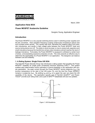
The peak current through the Power MOSFET during avalanche (IAS), the junction temperature at the start of the UIS pulse (Tj), and the time the Power MOSFET remains in avalanche (tAV).
An actual breakdown voltage in applications is chosen as 1.3 times the rated low current breakdown voltage.
It can be approximated using a formula that considers the pulse width (t1) and the period of the power pulse (t2), incorporating steady state thermal resistance.