
This paper discusses how to improve the power performance of the SuperSOTTM-6 Power MOSFET by optimizing the design of copper mounting pads. By using the thermal solution suggested in the document, users can take full advantage of the exceptional performance features of Fairchild Semiconductor's latest Power MOSFET, including very low on-resistance and improved junction-to-case thermal resistance (RθJC). This ultimately leads to improved component performance and higher circuit board packing density.
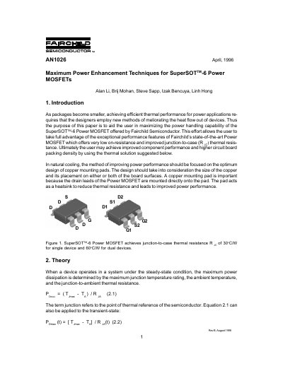
This document provides guidelines for maximizing the power handling capability of Fairchild Semiconductor's SuperSOT-6 Power MOSFETs. It focuses on improving thermal performance through the design of copper mounting pads on printed circuit boards (PCBs). The text explains that efficient thermal performance in smaller packages requires new methods to meliorate heat flow, specifically by utilizing the copper pad as a heatsink to reduce junction-to-case thermal resistance.
| Junction-to-case thermal resistance (dual devices) | 60°C/W |
|---|
It is recommended to put extra copper on the bottom of the board connected to the top pad by through-hole thermal vias.
A copper pad of 0.01 square inches on the top side achieves approximately 0.9W.
The junction-to-ambient thermal resistance lowers from approximately 160°C/W to 90°C/W.
The package achieves a junction-to-case thermal resistance of 30°C/W.