
This document introduces how to maximize the power handling capability of SOT-223 Power MOSFETs. This document provides the optimum design method of copper mounting pads to improve component performance and circuit board packing density.
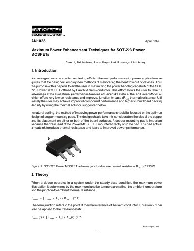
This document provides guidelines for maximizing the power handling capability of Fairchild's SOT-223 Power MOSFETs by optimizing copper mounting pad design on circuit boards. It explains that efficient thermal performance in smaller packages requires new methods to improve heat flow out of the device.
The text presents results from an investigation into the size and placement of 2 oz copper mounting pads. It demonstrates that increasing the copper pad area significantly lowers junction-to-ambient thermal resistance and that placing the copper on the top side of the board yields the best thermal performance.
A 0.066 square inch copper pad directly under the package is recommended to achieve approximately 1.3W power dissipation.
Using a 0.066 square inch copper mounting pad on the top side of the board achieves approximately 1.3W of maximum power dissipation.