
The MC10E/100E256 is a 3-bit 4:1 multiplexer with transparent latches and differential outputs. When the Latch Enable (LEN) is LOW, the latch is transparent, and output data is controlled by the multiplexer select controls. A logic HIGH on LEN latches the outputs. The Master Reset (MR) overrides all other controls to set the Q outputs LOW.
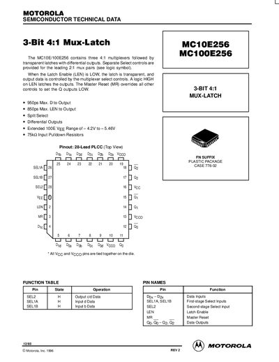
This document is a technical datasheet for the Motorola MC10E256 and MC100E256 integrated circuits. The device contains three 4:1 multiplexers followed by transparent latches with differential outputs. It features separate select controls for leading 2:1 mux pairs, a latch enable input, and a master reset function.
| Package Type | 28-Lead PLCC |
|---|---|
| Max Delay D to Output | 950ps |
| Max LEN to Output | 850ps |
| Input Pulldown Resistors | 75kQ |
The extended VEE range for the MC100E series is from -4.2V to -5.46V.
The Master Reset overrides all other controls to set the Q outputs LOW.