
MC10E/100E141 is an 8-bit full-function shift register. It performs serial/parallel in and serial/parallel out, shifting in either direction. The eight inputs D0-D7 accept parallel input data, while DL/DR accept serial input data for left/right shifting. The Qn outputs do not need to be terminated for the shift operation to function. To minimize noise and power, any Q output not used should be left unterminated.
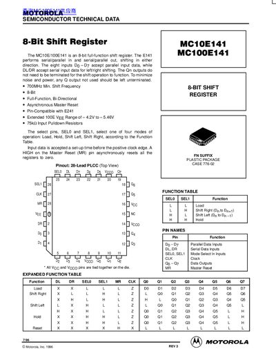
This document is a technical datasheet for the Motorola MC10E141 and MC100E141, which are 8-bit full-function shift registers. The devices support serial-in/serial-out, serial-in/parallel-out, and parallel-in/parallel-out operations, with the ability to shift data in either direction. Key features include a minimum shift frequency of 700 MHz, asynchronous master reset, and compatibility with the E241 series.
| Shift Frequency | 700 MHz Min. |
|---|---|
| Package Type | 28-Lead PLCC |
| VCC Range | 4.5V to 5.5V |
| Max Shift Frequency (0C) | 700 MHz |
| Max Shift Frequency (85C) | 900 MHz |
The device operates in four modes: Load, Hold, Shift Left, and Shift Right, selected by SELO and SEL1 pins.
A HIGH on the Master Reset (MR) pin asynchronously resets all registers to zero.