
The IDT29FCT520AT/BT/CT/DT and IDT29FCT521AT/ BT/CT/DT each contain four 8-bit positive edge-triggered registers. These may be operated as a dual 2-level or as a single 4-level pipeline. A single 8-bit input is provided and any of the four registers is available at the 8-bit, 3-state output. These devices differ only in the way data is loaded into and between the registers in 2-level operation. The difference is illustrated in Figure 1. In the IDT29FCT520AT/BT/CT/DT when data is entered into the first level (I = 2 or I = 1), the existing data in the first level is moved to the second level. In the IDT29FCT521AT/BT/CT/DT, these instructions simply cause the data in the first level to be overwritten. Transfer of data to the second level is achieved using the 4-level shift instruction (I = 0). This transfer also causes the first level to change. In either part I=3 is for hold.
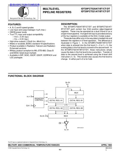
The document provides a technical description of the IDT29FCT520AT/BT/CT/DT and IDT29FCT521AT/BT/CT/DT devices. These are multilevel pipeline registers containing four 8-bit positive edge-triggered registers that can be operated as either a dual 2-level or a single 4-level pipeline. The text explains the functional differences between the two models regarding data loading and shifting operations.
| Number of Registers | Four 8-bit positive edge-triggered registers |
|---|---|
| Operating Temperature (Commercial) | 0 to +70 °C |
| Supply Voltage (Typical) | 5.0V |
| Input Capacitance | 6 to 10 pF |
| Output Capacitance | 8 to 12 pF |
They may be operated as a dual 2-level or as a single 4-level pipeline.
They differ in how data is loaded into and between registers during 2-level operation; the 520 shifts existing data while the 521 overwrites it.
The devices are available in DIP, SOIC, SSOP, QSOP, CERPACK and LCC packages.