
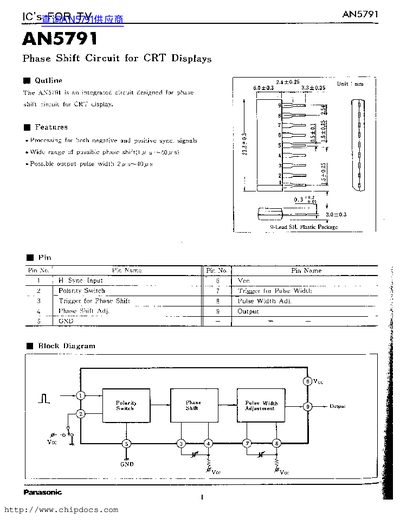
The document provides technical specifications and application details for the AN5791 IC. It is an integrated circuit specifically designed to function as a phase shift circuit for Cathode Ray Tube (CRT) display systems.
Key features include the ability to process both negative and positive sync signals, offering a wide range of possible phase shifts between 0 and 40 degrees. The device also supports adjustable output pulse widths ranging from 2 microseconds to 50 microseconds.
| Power Dissipation | 640 mW |
|---|---|
| Operating Ambient Temperature | -20~+70 Cc |
| Phase Shift Time (typical) | 5.0 us |
| Output Pulse Width (typical) | 4.9 us |
Yes, it can process both negative and positive sync signals.
The AN5791 is an integrated circuit designed for use as a phase shift circuit in CRT displays.
The typical phase shift time is 5.0 us when the supply voltage is 11 V.