
The AS91L1006BU is a one-to-6-port JTAG gateway. It partitions a single JTAG chain into six separate chains. These separate chains can be optionally configured to operate as a single chain. The AS91L1006BU device is used to provide enhanced capabilities to the standard IEEE1149.1. It enables the IEEE1149.1 interface to be used in a true Multi-Drop environment without any additional signals. This Multi-Drop capability enables the standard IEEE1149.1 interface to be used not just for stand-alone PCB (Printed Circuit Board) testing, but also for complete system testing including all PCBs within a system back plane environment. The AS91L1006BU provides the capability of partitioning the PCB into multiple smaller IEEE1149.1 scan chains totally under software control. Partitioning the IEEE1149.1 chains on the PCB has several benefits including easier fault diagnostics capabilities as a fault on one of the IEEE1149.1 Local Scan Ports (LSPs) does not render the PCB untestable, faster flash programming on the PCBs, and removal of IEEE1149.1 signal loading issues. All of the protocols required for addressing the AS91L1006BU device via the Multi-Drop capability and the protocols for configuring which of the six IEEE1149.1 LSPs on the AS91L1006BU are to be used, is handled via 3rd party ATPG tools from vendors like Asset-Intertech and JTAG Technologies. In a Multi-Drop environment it is also possible to perform interconnect test
The AS91L1006BU is a one‑to‑6‑port JTAG gateway that partitions a single IEEE 1149.1 chain into up to six independent local scan ports (LSPs). It enables multi‑drop testing of back‑plane systems without additional signals, allowing fault isolation, faster flash programming, and reduced signal loading.
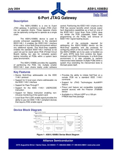
The device includes a 16‑state TAP controller, address selection logic, and several configurable registers (e.g., MCGR, AUTOWR, MODE_SELECT) that control scan‑chain routing, pass‑through mode, and asynchronous reset testing. It is offered in 100‑pin LQFP or FPBGA lead‑free packages and serves as a second‑source replacement for the Firecron JTSO6BU.
| Number of JTAG ports | 6 |
|---|---|
| Package options | 100‑pin LQFP or 100‑pin FPBGA lead‑free |
| AUTOWR register width | 6‑bit |
It supports six local scan chains addressable via the IEEE 1149.1 interface.
The AUTOWR register, a 6‑bit register, controls the pass‑through of the AutoWR signal to any LSP.
The device is offered in a 100‑pin LQFP package and a 100‑pin FPBGA lead‑free package.