
Instruction manual for TP40A micro-computer digital indicating controller, mainly introduces the features and usage of TP40A
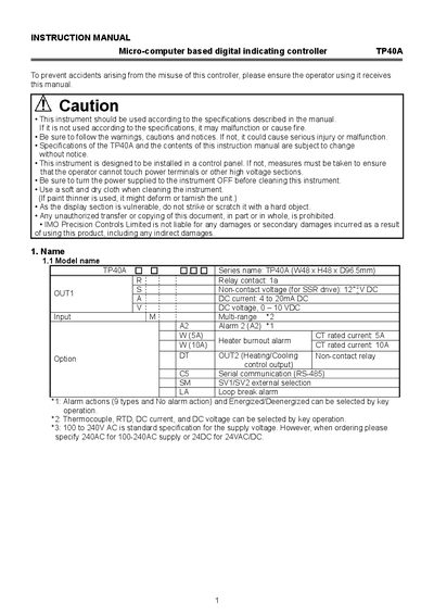
This manual covers safety precautions, mounting, wiring and configuration of the TP40A digital indicating controller. It emphasizes proper power‑off procedures, clean handling, and environmental requirements before installation.
The document details the controller's hardware layout, input types, communication options, parameter settings, and a comprehensive troubleshooting guide to help users diagnose sensor or output issues.
| Physical dimensions | W48 x H48 x D96.5 mm |
|---|---|
| Relay contact rating | 1 A |
| Non‑contact voltage (SSR drive) | 12 V DC |
| DC current input range | 4 to 20 mA DC |
| DC voltage input range | 0‑10 V DC |
| Supply voltage | 100‑240 V AC (standard) |
| Current transformer (CT) rating | 5 A or 10 A (options) |
| Serial communication | RS‑485 |
| Maximum RS‑485 nodes | 31 units per host |
| Recommended fuse | Time‑lag, 250 V AC, 2 A |
Turn the power off, use a soft dry cloth, and avoid paint thinner which can damage the unit.
The terminal block is designed to be wired from the left side; insert the lead wire from the left side and fasten it with the terminal screw.
A time‑lag fuse rated at 250 V AC and 2 A is recommended.
Up to 31 units can be connected to a single host computer.