
This document describes the features and characteristics of the Hydraulic Inductive Position Transducer - Hydraulic Series LVDT. The sensors are designed for use in hydraulic cylinders with a maximum pressure resistance of up to 400 bar. They are particularly suitable for harsh industrial environments where high electromagnetic tolerance is required. The sensor is unaffected by electrical or magnetic fields and enables a connection between hydraulic cylinders and machine controls. Customized versions with different measurement ranges and flange types are available.
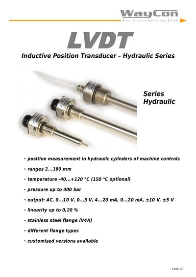
The WayCon LVDT 23.06.10 is an inductive position transducer designed for hydraulic cylinders in demanding industrial environments. It measures travel from 2 mm to 180 mm, tolerates pressures up to 400 bar, and operates from –40 °C to +120 °C (optional up to +150 °C). The sensor provides a stainless‑steel (V4A) flange and can be supplied with various flange thread sizes (M18, M30).
Installation is performed via a DIN‑rail‑mountable external electronics unit (IMCA) with either 4‑core TPE cable or PTFE cable. The cable length may reach 100 m, and the sensor housing is grounded to the machine frame. Zero‑point and gain adjustments are made on the external electronics, and output polarity can be inverted by swapping specific clamps.
| Measurement range | 2 mm … 180 mm |
|---|---|
| Maximum pressure | 400 bar |
| Operating temperature | -40 °C … +120 °C (optional +150 °C) |
| Output signals | AC, 0‑10 V, 0‑5 V, 4‑20 mA, 0‑20 mA, ±10 V, ±5 V |
| Linearity | up to 0.20 % of full scale |
| Flange material | Stainless steel (V4A) |
| Power supply | 9 V … 36 V DC |
| Current consumption | 75 mA at 24 VDC |
| Maximum cable length | 100 m |
| Housing material | Polyamide PA6.6 (UL94‑VO) |
It can resist pressures up to 400 bar.
Swap clamps 6 and 8 on the external electronics to invert the output.
The cable length should not exceed 100 m.
The sensor provides AC, 0‑10 V, 0‑5 V, 4‑20 mA, 0‑20 mA, ±10 V and ±5 V outputs.