
This datasheet provides the technical specifications of the BUP 213 IGBT, including maximum ratings, dynamic characteristics, and static characteristics.
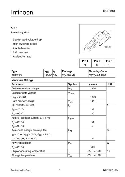
The BUP 213 is a 1200 V, 32 A IGBT offered in a TO‑220AB package. It features low forward voltage drop, high switching speed, low tail current, and latch‑up‑free operation, making it suitable for high‑power applications.
The datasheet lists maximum ratings such as VCEO = 1200 V, IC = 32 A (25 °C), VGE = +20 V, and a power dissipation of 200 W at 25 °C. Thermal resistance from chip to case is under 0.63 K/W. Switching characteristics include turn‑on delay ~70 ns, rise time ~45 ns, turn‑off delay ~400 ns, and fall time ~70 ns. Package dimensions and pinout are also provided.
| Collector‑emitter voltage (VCEO) | 1200 V |
|---|---|
| Continuous collector current (IC) at 25 °C | 32 A |
| Gate‑emitter voltage (VGE) | +20 V |
| Power dissipation at 25 °C | 200 W |
| Thermal resistance, chip‑to‑case | < 0.63 K/W |
The maximum collector‑emitter voltage is 1200 V.
The device can handle up to 32 A of collector current at 25 °C.
The thermal resistance is less than 0.63 K/W.