
Mitsubishi Electric PM75RL1B120 Intelligent Power Module User Manual

This document describes the features and characteristics of the MITSUBISHI PM75RL1B120 flat-base type insulated package released in May 2009. It includes the adoption of a new 5th generation Full-Gate CSTBTTM chip, the over-temperature protection that detects the chip surface temperature of CSTBTTM, the possibility of error output signal from all each protection upper and lower arm of IPM, and compatibility with L-series package. It is suitable for general purpose inverters, servo drives, and other motor control applications.
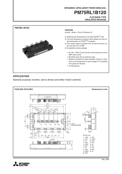

Mitsubishi Electric PM75RL1B120 Intelligent Power Module User Manual - cover page
Brand
Mitsubishi
Category
Power Management
Document type
User Manual
Language
English
Pages
9
File format
PDF
File size
145 KB
Published
22 March, 2012
Updated
29 September, 2023
MD5 checksum
84685036E378DBA390552D398D6BEB8D

About this manual

This manual describes the features, electrical and mechanical ratings, and recommended operating conditions for the Mitsubishi Electric PM75RL1B120 Intelligent Power Module. It includes block diagrams, maximum ratings, and detailed performance curves for inverter, brake, and control sections.

Precautions for testing, PCB layout recommendations, and wiring diagrams are also provided to ensure safe and reliable integration of the module in general‑purpose inverter, servo drive, and motor control applications.

What's inside

  • Feature Overview
  • Maximum Ratings
  • Brake Part Specifications
  • Control Part Specifications
  • Mechanical Ratings and Characteristics
  • Recommended Conditions for Use
  • Precautions for Testing
  • Performance Curves
  • Switching Loss Characteristics
  • Normalized Transient Characteristics

Specifications

Collector Current (Ic)75 A
Junction Temperature (Tj)-20 °C ~ +150 °C
Weight340 g
Supply Voltage (Vcc)800 V

Frequently asked questions

What is the maximum continuous collector current for the inverter part?

The inverter part is rated for a continuous collector current of 75 A at 25 °C.

What is the recommended supply voltage for the module’s power bus?

The recommended supply voltage across the P‑N terminals is 800 V.

What are the temperature limits for safe operation?

The module can operate from –20 °C up to +150 °C junction temperature.

Download PDF (145 KB)

More Mitsubishi Manuals


View all Mitsubishi manuals →