
TB6575FNG User Manual, This datasheet details the TB6575FNG usage methods, including power supply voltage, control input, oscillation circuit, application circuit, power capacitor, etc.
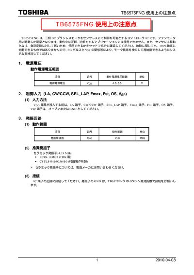
This document provides detailed usage notes for the Toshiba TB6575FNG controller IC, which drives three‑phase DC brushless motors in sensor‑less mode. It explains the recommended power‑supply range, input pin handling, oscillator selection, and various application circuits for fan‑motor use.
Key topics include start‑up configuration, phase‑angle control, overlap‑power techniques, and level‑shift methods for comparator circuits when operating above 30 V motor voltage. The notes also give practical component values and calculation formulas for over‑current detection and filtering. This manual is written in Japanese.
| Control supply voltage (Vpp) | 4.5‑55 V |
|---|---|
| Oscillator frequency (fosc) | 2^8 MHz (256 MHz) |
| Recommended crystal | 4.19 MHz ceramic (TDK or Murata) |
| Vcc‑GND decoupling capacitor | 10 pF‑38 nF electrolytic |
| VM‑GND decoupling capacitor | 0.001 pF‑0.22 pF ceramic |
| Start resistor (R1) | 220 kΩ |
| SC:C1 capacitor | 0.47 nF ceramic |
| Over‑current detection resistor calculation | R = Voc / Iout |
The controller operates with a Vpp supply voltage between 4.5 V and 55 V.
The device uses an oscillator frequency of 2^8 MHz (256 MHz).
A 4.19 MHz ceramic crystal, such as TCR4.19MCS (TDK) or CSTLS4M19GS6‑B0 (Murata), is recommended.
Use R = Voc / Iout, where Voc is the voltage across the sense resistor at the over‑current threshold.