
Installation guide for the Thermaltake TT Sync Controller TT Premium Edition: component connections, PWM/SATA power wiring, mainboard signal bridging.
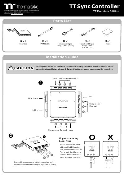
The Thermaltake TT Sync Controller TT Premium Edition installation guide lists the controller, three PWM cables, mainboard signal bridge cables for ASUS and GIGABYTE, Velcro, and the guide. It says to connect component cables to the controller in numerical order starting at port 1, which is marked with a dot, and warns users to power off the PC and check the positive and negative ends on the connector before connecting a cable to the mainboard.
The guide shows connecting the PWM cable to a 4-pin PWM mainboard header and the controller, and connecting the power cable to a SATA connector and the controller. It also notes that when using Lumi Plus, other addressable LED devices should be connected first and the Lumi Plus last, and it describes using the mainboard signal bridge cable to connect controllers for LED color control through mainboard software, referencing ASUS Aura Addressable Strip Header(s) and GIGABYTE RGB Fusion with Digital LEDs.
| Mainboard PWM connection | 4-pin PWM |
|---|---|
| Power connection | SATA connector |
Power off the PC and check the positive and negative ends on the connector; connecting the wrong end can damage the controller.
Connect them in numerical order onto the controller, starting with port 1, which is marked with a dot.
Connect the power cable to the SATA connector and to the controller.
It can connect controllers when you want to control LED color via mainboard software.