
The Harris datasheet provides specifications, ratings, and performance curves for the IRF120, IRF121, IRF122, and IRF123 N‑Channel power MOSFETs.
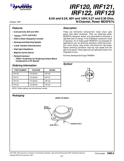
This document describes the IRF120, IRF121, IRF122 and IRF123 N‑Channel enhancement mode silicon‑gate power MOSFETs. They are intended for high‑speed switching applications such as regulators, converters, motor drivers and relay drivers.
Key specifications, absolute maximum ratings, electrical characteristics and typical performance curves are presented, together with test circuit diagrams for evaluating switching behavior, on‑resistance, capacitances and thermal performance.
| Drain‑to‑Source Voltage (VDS) | 100 V (IRF120, IRF122), 80 V (IRF121, IRF123) |
|---|---|
| On‑Resistance (rDS(on)) | 0.27 Ω (IRF120, IRF121), 0.36 Ω (IRF122, IRF123) |
| Maximum Power Dissipation (PD) | 60 W |
| Thermal Resistance, Junction‑to‑Case (θJC) | 2.5 °C/W |
| Operating Temperature Range | –55 °C to 175 °C |
The IRF120 is rated for a maximum drain‑to‑source voltage of 100 V.
The IRF123 has an on‑resistance of about 0.36 Ω.
These devices are sensitive to electrostatic discharge, so proper ESD handling procedures should be followed.