
This document introduces the power supply for clutches and brakes. The power supply has different models and specifications, suitable for clutches and brakes with different voltages. The document lists the characteristics and applications of various models.
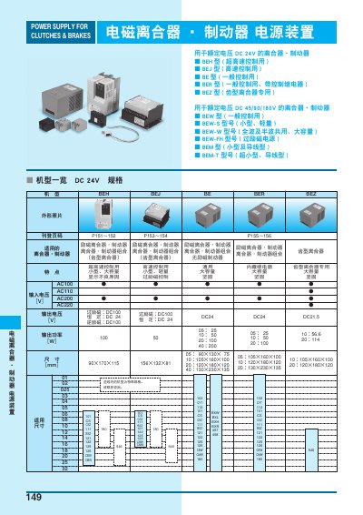
This manual provides specifications, wiring diagrams, protection functions and operating instructions for the electromagnetic clutch and brake power supply units. It covers a range of models (BEH, BEJ, BE, BER, BEZ, BEW, etc.) and explains how to select, install and operate the units safely.
The document includes details on input voltage options, output voltage regulation, protection features such as over‑current and over‑voltage detection, and guidance on single‑action and dual‑action control modes. This manual is written in Chinese.
| Output voltage (constant excitation) | DC 24 V |
|---|---|
| Over‑excitation voltage | DC 100 V (for AC100V input) / DC 180 V (for AC200V input) |
| Output power (continuous) | 25 W (typical) |
| Operating temperature range | -10 °C to +50 °C |
The constant excitation voltage is DC 24 V.
Yes, the power supply includes an internal over‑current protection circuit that stops the output when a fault is detected.
Yes, it can be configured for single‑action (individual clutch or brake control) or dual‑action (combined clutch‑brake control) modes, but both modes cannot be active simultaneously.