
The CDC582 is a high-performance, low-skew, low-jitter clock driver. It uses a phase-lock loop (PLL) to precisely align the frequency and phase of the clock output signals to the differential LVPECL clock (CLKIN, CLKIN) input signals. It is specifically designed to operate at speeds from 50 MHz to 100 MHz or lower.
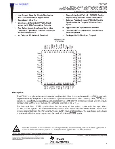
The CDC582 is a high-performance, low-skew, low-jitter clock driver designed to distribute differential LVPECL clock inputs to twelve TTL-compatible outputs. It utilizes an internal phase-lock loop (PLL) to align the frequency and phase of the output signals to the input signals, operating at 3.3 V.
| Supply Voltage | 3.3 V |
|---|---|
| Operating Temperature Range | 0°C to 70°C |
| Operating Frequency Range | 50 MHz to 100 MHz |
| Output Frequency Range | 25 MHz to 100 MHz |
| Package Type | 52-Pin Quad Flatpack |
No, the CDC582 does not require external RC networks as the loop filter is included on the chip.
The TEST pin is used for factory testing and can bypass the PLL circuitry.