
the cdc2509c is a 3.3v phase-lock loop clock driver from ti. the device supports frequencies from 25mhz to 125mhz and offers low distortion and jitter.
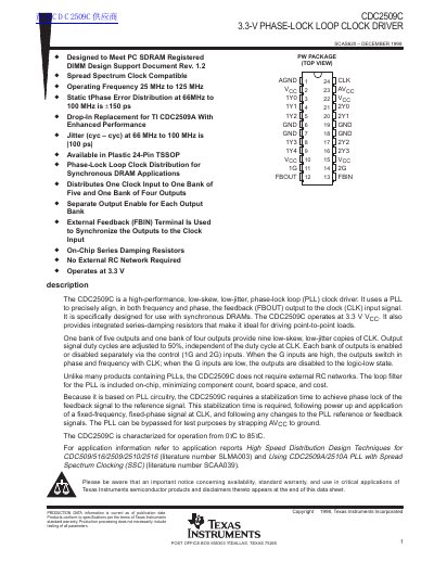
The CDC2509C is a high-performance, low-skew, low-jitter phase-lock loop (PLL) clock driver designed specifically for synchronous DRAM applications. It operates at 3.3 V and provides integrated series-damping resistors, making it ideal for driving point-to-point loads without requiring external RC networks. The device distributes one clock input to one bank of five outputs and one bank of four outputs, with separate output enable controls for each bank.
| Operating Voltage | 3.3 V |
|---|---|
| Operating Temperature | 0°C to 85°C |
| Clock Frequency | 25 MHz to 125 MHz |
| Package Type | 24-Pin TSSOP |
No, the CDC2509C does not require external RC networks as the loop filter is included on-chip.
It provides one bank of five outputs and one bank of four outputs, totaling nine outputs.
Yes, the PLL can be bypassed by strapping AVcc to ground.