
Lowrance RIM 100 Radar Interface Module Installation Instructions

This document provides installation instructions for the Radar & RIM 100 Radar Interface Module, a radar product from Lowrance Electronics, Inc. The document describes the characteristics of radar waves, potential issues and interference, and provides considerations for installation location and dip angle requirements.
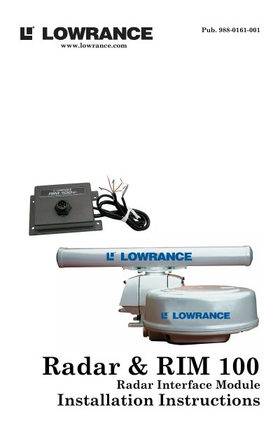

Lowrance RIM 100 Radar Interface Module Installation Instructions - cover page
Brand
Lowrance
Category
Other device
Document type
Installation Guide
Language
English
Pages
28
File format
PDF
File size
708 KB
Published
11 July, 2012
Updated
28 September, 2023
Model
RIM 100
MD5 checksum
064A67912D7F9A3736ACE46425FCAF65

About this manual

This manual provides installation instructions for the Lowrance RIM 100 Radar Interface Module, which connects a radar scanner unit to a display unit. It includes important safety warnings regarding high voltage and microwave radiation, as well as guidelines for selecting an installation location to ensure maximum performance and safety for crew.

What's inside

  • Warnings and Cautions
  • What is radar?
  • Antenna
  • Side lobe
  • Characteristics of Radar Wave
  • Targets difficult to display on screen
  • Radar Shadow Zones
  • False echoes
  • Radar interference
  • Installation Considerations

Frequently asked questions

What is the minimum distance required between the radar antenna and people below?

The radar antenna must be installed a minimum distance of 1 foot (0.3 m) or more above all persons.

Is there any internal adjustment needed when installing the scanner unit?

No, there are no internal connections or adjustments necessary for installation.

Download PDF (708 KB)

More Lowrance Manuals


View all Lowrance manuals →