
This document introduces the installation instructions for the RIM 300 radar interface module
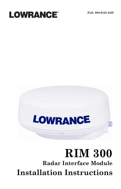
This document provides installation instructions for the Lowrance RIM 300 Radar Interface Module. The module is designed to replace the original power cable on compatible display units, integrating radar data, power, and NMEA 2000 communication into a single connector.
The guide details the wiring process, including connecting the red and black wires for display unit power (requiring a 3-amp fuse) and using the blue and green wires to exchange GPS position data with NMEA 0183-compatible devices. It also covers powering an NMEA 2000 network or LGC-3000 antenna module.
The red lead must be fused with a 3-amp fuse.
Yes, you must purchase a SIMRAD heading sensor for this feature to work properly.