
The MC10/100EL34 is a low skew ÷2, ÷4, ÷8 clock generation chip designed explicitly for low skew clock generation applications
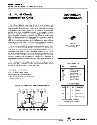
The Motorola MC10EL34/MC100EL34 is a low skew clock generation chip designed for applications requiring precise alignment of common output edges. The device features internal synchronous dividers that can be driven by differential or single-ended ECL or PECL input signals. It includes a common enable input that is synchronous to avoid generating runt clock pulses and a master reset input for synchronizing internal dividers and multiple devices in a system.
The chip is available in a D suffix plastic SOIC package (Case 751B-05). Key specifications include a maximum toggle frequency of 1100 MHz, output-to-output skew of 50 ps, and greater than 1000V ESD protection. The datasheet provides AC/DC characteristics, timing diagrams, pin descriptions, and outline dimensions.
| Output-to-Output Skew | 50 ps |
|---|---|
| Maximum Toggle Frequency | 1100 MHz |
| Internal Inout Pulldown Resistors | 75kQ |
| ESD Protection | >1000V |
| Package Type | Plastic SOIC Package |
| Case Number | 751B-05 |
The device can be driven by either a differential or single-ended ECL or, if positive power supplies are used, PECL input signal.
The common enable is synchronous so that the internal dividers will only be enabled/disabled when the internal clock is already in the LOW state.
The master reset input allows for the synchronization of the internal dividers, as well as multiple EL34s in a system.