
This is a summary of the MC10E/100E112 datasheet. It is a quad driver with two pairs of OR/NOR outputs from each gate, and a common, buffered enable input. The device can be used as an ECL memory address fan-out driver, or as a clock driver, although the MC10E/100E111 is specifically designed for this purpose, and offers lower skew than the E112. For memory address driver applications where scan capabilities are required, please refer to the E212 device.
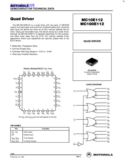
The MC10E112 and MC100E112 are quad driver devices designed with two pairs of OR/NOR outputs from each gate and a common, buffered enable input. These devices can function as ECL memory address fan-out drivers or as clock drivers when using only the enable input. The MC100E112 variant supports an extended VEE range of -4.2V to 5.46V.
| Propagation Delay Max | 600ps |
|---|---|
| Package Type | 28-Lead PLCC |
| Input Pulldown Resistors | 75kQ |
| VEE Range (100E) | -4.2V to 5.46V |
The maximum propagation delay is 600 ps.
The extended VEE range is from -4.2V to 5.46V.
The device uses a 28-lead PLCC package.