
Describes the installation methods of 50-682SM and 50-682SF metal flex connectors, including pairing, installing anti-short bushings, wiring through male metal flex connectors, installing wires into disconnect, pushing disconnect into metal flex connector, inserting flex cables into the back end of metal flex connector, and tightening screws
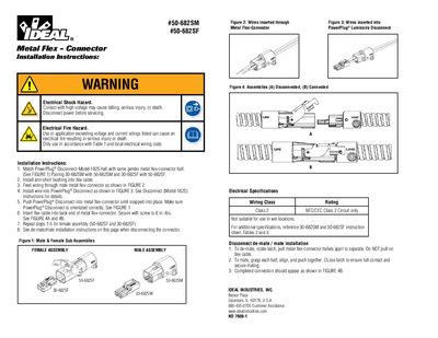
This document provides installation instructions for the Ideal Industries Model -682S Metal Flex-Connector. It details how to assemble male and female sub-assemblies (Models 30-682SM/SF and 50-682SM/SF) by matching genders, installing anti-short bushings, feeding wiring through the connector, and securing the PowerPlug Disconnect. The guide includes warnings regarding electrical shock hazards and fire risks if voltage or current ratings are exceeded.
Secure the flex cable with a screw tightened to 8 in.-lbs.
This connector is rated for Class 2 NEC/CEC Class 2 Circuit only.
To de-mate, rotate the latch and pull the metal flex-connector halves apart.