
5474/DM5474/DM7474 Dual Positive-Edge-Triggered D Flip-Flops with Preset/Clear and Complementary Outputs
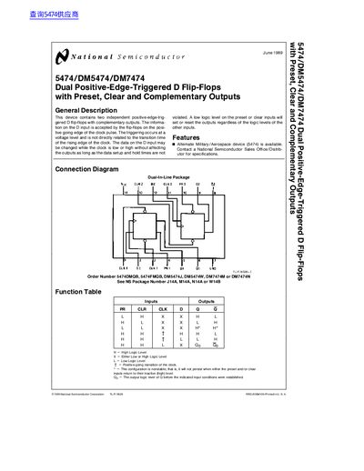
This document describes the 5474/DM5474/DM7474 Dual Positive-Edge-Triggered D Flip-Flops, which contain two independent flip-flops with complementary outputs. The device accepts information on the D input on the positive-going edge of the clock pulse and allows data changes while the clock is low or high, provided setup and hold times are met.
| High Level Input Voltage (DM54/DM74) | 2V / 2V |
|---|---|
| Low Level Input Voltage (DM54/DM74) | 0.8V / 0.8V |
| Operating Temperature Range (DM54/DM74) | -55°C to +125°C |
| Storage Temperature Range (DM74) | -65°C to +150°C |
| High Level Output Voltage (DM54) | 2.4V min |
| Low Level Output Voltage (DM74) | 0.4V max |
Yes, the device contains two independent positive-edge-triggered D flip-flops with preset, clear and complementary outputs.
The maximum clock frequency is 15 MHz.
The maximum supply voltage is 5.5 V.
The minimum input setup time is 20 ns.