
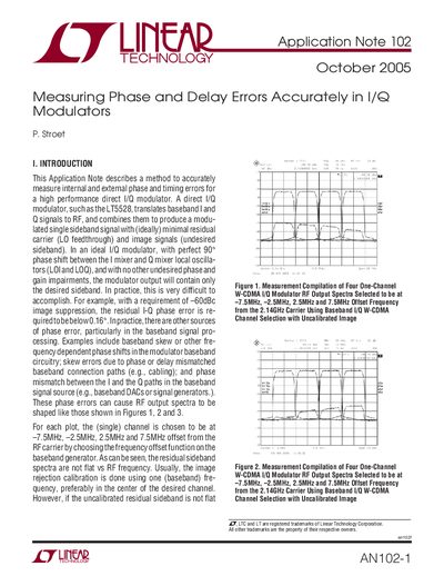
This Application Note describes a method to accurately measure internal and external phase and timing errors for a high performance direct I/Q modulator. A direct I/Q modulator, such as the LT5528, translates baseband I and Q signals to RF, and combines them to produce a modulated single sideband signal with (ideally) minimal residual carrier (LO feedthrough) and image signals (undesired sideband). In an ideal I/Q modulator, with perfect 90° phase shift between the I mixer and Q mixer local oscillators (LOI and LOQ), and with no other undesired phase and gain impairments, the modulator output will contain only the desired sideband. In practice, this is very difficult to accomplish. For example, with a requirement of –60dBc image suppression, the residual I-Q phase error is required to be below 0.16°. In practice, there are other sources of phase error, particularly in the baseband signal processing. Examples include baseband skew or other frequency dependent phase shifts in the modulator baseband circuitry; skew errors due to phase or delay mismatched baseband connection paths (e.g., cabling); and phase mismatch between the I and the Q paths in the baseband signal source (e.g., baseband DACs or signal generators.). These phase errors can cause RF output spectra to be shaped like those shown in Figures 1, 2 and 3.
This document details how to measure phase and delay errors in direct I/Q modulators, such as the LT5528. It explains that residual sideband spectra are shaped by various error sources, including baseband skew, connection path delays, and mismatches between local oscillators (LOI and LOQ). The note illustrates how these errors affect image rejection calibration across different frequencies.
This document describes a method to accurately measure internal and external phase and timing errors for a high performance direct I/Q modulator.
To achieve -60dBc image suppression, the residual I/Q phase error must be below 0.16°.
The single channel is chosen at -7.5MHz, -2.5MHz, 2.5MHz and 7.5MHz offset from the RF carrier.