
Linear Technology AN97-1 Accurate Measurement of LT5514 Third Order Intermodulation Products Application Note

This application note describes a method for accurately measuring the third order intercept point for low distortion IC products such as the LT5514. This includes the test setup, test equipment, test signal and interpretation of the measurement results.
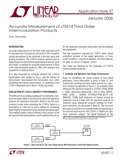

Linear Technology AN97-1 Accurate Measurement of LT5514 Third Order Intermodulation Products Application Note - cover page
Brand
Linear Technology
Category
Other Electronics
Document type
Application Note
Language
English
Pages
8
File format
PDF
File size
94 KB
Published
05 June, 2012
Updated
30 September, 2023
MD5 checksum
F3D6DDC591755A450580915CC0997852

About this manual

The document describes precautions and procedures required to evaluate the linearity performance of low distortion ICs like the LT5514. It details a two-step evaluation method: first optimizing the test setup with signal generators, combiners, and attenuators, and secondly evaluating the LT5514 demo board performance by adjusting gain and net attenuation.

What's inside

  • Introduction
  • Evaluation of Linearity Performance
  • Evaluate and Optimize Test-Setup Performance
  • Evaluate the Demo Board Performance
  • Demo-Board Output Linearity vs Device Linearity

Frequently asked questions

What input power level should be set for the two-tone test signal?

The two-tone test signal should be set to a power level of –23dBm.

What resistor must be removed from the demo board when no transmission lines are expected?

Matching resistor R7 (255 Ω) must be removed from the LT5514 demo board.

What is the output impedance of the demo board when resistor R7 is open?

The differential output impedance is 200Ω when R7 is open.

Download PDF (94 KB)

More Linear Technology Manuals


View all Linear Technology manuals →