
Slew rate verification for wideband amplifiers
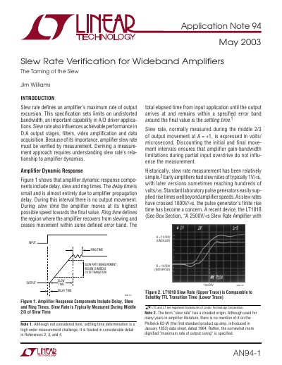
The document defines slew rate as an amplifier's maximum output excursion speed and its importance in A/D driver applications. It details how standard laboratory pulse generators often fail to accurately measure modern high-speed amplifiers due to their own finite rise times.
To address this, the note presents a circuit design for a subnanosecond rise time pulse generator using avalanche operation. This alternative allows for accurate verification of slew rate limiting in devices such as the LT1818.
| Gain – Bandwidth Product (Typ) | 400MHz |
|---|---|
| Full Power Bandwidth (Typ) | 95MHz |
| Slew Rate (Typ) | 2500V/ ms |
| Delay (Typ) | 1ns |
| Settling Time to 0.1% (Typ) | 10ns |
The typical slew rate for the LT1818 is 2500V/ms.
As amplifier slew rates cross 1000V/ms, the finite rise time of standard pulse generators becomes a concern that limits accurate measurement.
The circuit described in Figure 8 produces pulses with a rise time of 360ps.