
This document is the datasheet of DTD713ZE/DTD713ZM diodes, which has a low VCE (sat) and built-in bias resistors, which can be configured as a switch circuit without connecting external input resistors.
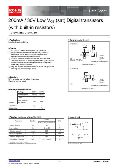
The ROHM DTD713ZE and DTD713ZM are low‑voltage, 200 mA digital NPN transistors that incorporate thin‑film bias resistors. They are intended for inverter, interface and driver circuits, offering lower saturation voltage and reduced parasitic effects.
The document provides electrical characteristics, packaging details (EMT3 / VMT3, SOT‑416), maximum ratings, and typical application circuits. It also includes legal notices and contact information for further product specifications.
| Collector‑emitter voltage (Vce) max | 30 V |
|---|---|
| Input voltage (Vin) | 5 V to 10 V |
| Power dissipation (Pp) | 150 mW |
| Junction temperature (Tj) max | 150 °C |
| Package type | EMT3 / VMT3 (SOT‑416) |
They are intended for inverter, interface and driver circuits.
They allow an inverter circuit to be built without external input resistors and reduce parasitic effects.
The maximum VCE is 30 V.