
DTC123TKA is a digital transistor from ROHM with a rated current and voltage of 200mA/50V. It has a built-in bias resistor and does not require an external input resistor to configure an inverter circuit. The transistor uses NPN epitaxial planar silicon transistor structure and has an external dimension of 2.8*1.6*0.4mm.
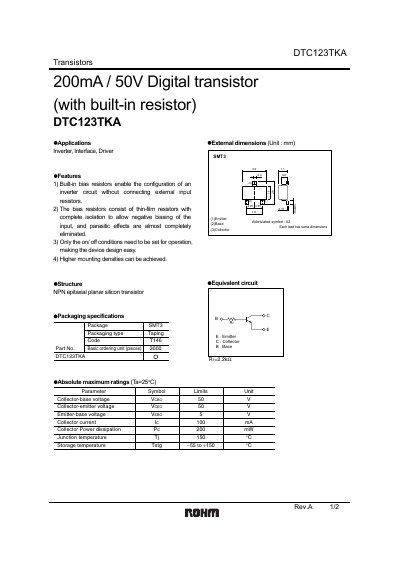
The DTC123TKA is an NPN epitaxial planar silicon transistor that incorporates a built‑in thin‑film bias resistor, allowing inverter, interface and driver circuits to be built without external input resistors. Its design provides high mounting density and simplifies circuit design.
The device is supplied in a SMT package (Part No. DTC123TKASMT3) with dimensions of 2.81 mm × 1.60 mm × 0.95 mm. Key electrical ratings include 50 V collector‑base and collector‑emitter voltages, 5 V emitter‑base voltage, 200 mA maximum collector current, and an operating temperature range of –55 °C to +150 °C.
| Collector‑base voltage (VCBO) | 50 V |
|---|---|
| Collector‑emitter voltage (VCEO) | 50 V |
| Emitter‑base voltage (VEB0) | 5 V |
| Operating temperature range | -55 °C to +150 °C |
| Built‑in resistor (R1) typical value | 2.2 kΩ |
The device can withstand up to 50 V between collector and base.
The built‑in bias resistor has a typical value of 2.2 kΩ.
It is rated for operation from –55 °C up to +150 °C.
It is used in inverter, interface and driver circuits.