
This document describes the ROHM digital transistors DTC115TM / DTC115TE / DTC115TUA / DTC115TKA, which have built-in resistors and their applications.
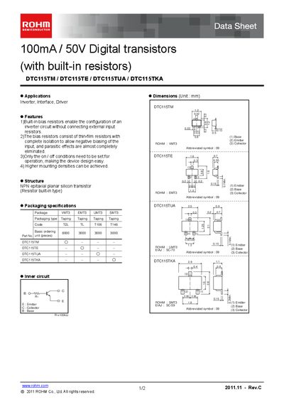
The DTC115 series are NPN epitaxial planar silicon digital transistors that incorporate built‑in thin‑film bias resistors. These devices are intended for inverter, interface, and driver circuits, allowing higher mounting densities and simplified design.
Key specifications include a collector‑base voltage of 50 V, collector‑emitter voltage of 50 V, emitter‑base voltage of 5 V, and a maximum collector current of 100 mA. The built‑in resistor value is 100 kΩ, and the parts are offered in VMT3, EMT3, UMT3, and SMT3 tape‑and‑reel packages.
| Collector‑emitter voltage (V_CEO) | 50 V |
|---|---|
| Emitter‑base voltage (V_EBO) | 5 V |
| Collector current (I_C) | 100 mA |
| Built‑in resistor (R_i) | 100 kΩ |
The built‑in resistor is 100 kΩ.
They are intended for inverter, interface, and driver circuits.
They are offered in VMT3, EMT3, UMT3, and SMT3 tape‑and‑reel packages.