
The IR1150 is a high-efficiency, low-power µPFC PFC control IC that employs IR’s proprietary “One Cycle Control” (OCC) technique. Based on IR’s proprietary “One Cycle Control” (OCC) technique, IR1150 provides a cost-effective solution for PFC. This proprietary control method allows major reductions in component count, PCB area and design time while delivering the same high system performance as traditional solutions. The IC is fully protected and eliminates the often noise-sensitive line voltage sensing requirements of existing solutions. IR1150 features include programmable switching frequency, programmable dedicated over voltage protection, brownout and output undervoltage protection, cycle-by-cycle peak current limit, soft start, user initiated micropower “Sleep Mode”, open loop protection, maximum duty cycle limit of 98%, user programmable fixed frequency operation, min. off time of 150-350ns over freq range, VCC under voltage lockout, internally clamped 13V gate drive, fast 1.5A peak gate drive, micropower startup (<200 µA), latch immunity and ESD protection.
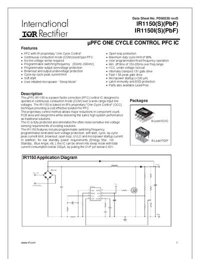
The IR1150(S)(PbF) and IR11501(S)(PbF) are power‑factor‑correction control ICs designed for boost converters operating in continuous conduction mode. They feature a proprietary One‑Cycle Control method, programmable switching frequency, soft‑start, and extensive protection functions.
The document provides absolute maximum ratings, recommended operating conditions, electrical characteristics, pin assignments, and mechanical data such as package dimensions and tape‑and‑reel information.
| Supply voltage (VCC) range | 15 V – 20 V |
|---|---|
| Programmable switching frequency | 50 kHz – 200 kHz |
| Maximum peak gate drive current | 1.5 A |
| Sleep mode current consumption | up to 200 µA |
| Gate low voltage (Voto) | 1.2 V – 1.5 V |
The device can be programmed to operate between 50 kHz and 200 kHz.
The gate driver can deliver a peak current of 1.5 A.
Sleep mode current is specified as up to 200 µA.
A supply voltage of 15 V to 20 V is recommended.