
This manual introduces the maintenance of DX-T9, DX-T7, DX-T5, including precautions, disassembly, adjustment and troubleshooting
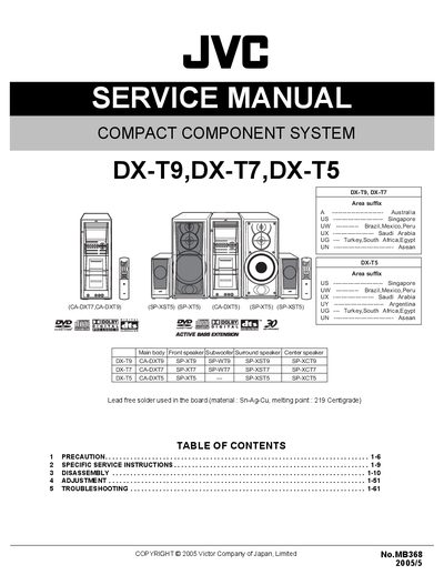
This service manual provides detailed instructions for servicing JVC's DX‑T9, DX‑T7 and DX‑T5 compact component systems. It includes safety precautions, part identification, and step‑by‑step procedures for disassembly, adjustment, and repair of the DVD changer mechanism, servo board, motor board, and other internal components.
The document is organized into sections on specific service instructions, component removal (e.g., DVD servo board, motor board, DVD pickup), and troubleshooting. Each procedure is illustrated with figures and notes on handling delicate parts such as solder joints and belts.
| Solder material | Sn‑Ag‑Cu, melting point 219 °C |
|---|
First solder the short land sections on the DVD pickup, then disconnect the card wires from connectors CN201 and CN451, remove the two screws B attaching the board, and release the lock of connector CN101 before pulling the board out.
Remove the two belts from the motor pulleys, unscrew the motor mounting screws, disconnect connector CN2 from the tray switch board, and then pull the motor board out of the assembly.