
This is a user manual for TA057 25 MHz ±1400 V Differential Probe
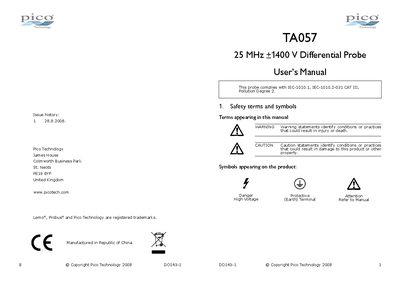
This manual explains how to safely install, power, and operate the TA057 differential probe. It covers safety symbols, grounding requirements, and proper handling to prevent electric shock, fire, or damage.
The document also lists the probe's technical specifications, such as bandwidth, attenuation, input impedance, and power options, and provides step‑by‑step test procedures to verify correct operation.
| Bandwidth | 25 MHz (-3 dB) |
|---|---|
| Attenuation ratio | 1:20 / 1:200 |
| Rise time | 14 ns |
| Input impedance | 4 MΩ // 5.5 pF each side to ground |
| Differential range | +1400 V DC+Peak AC or 1000 V RMS @ 1/200 |
| Absolute maximum voltage | +1400 V DC+Peak AC or 1000 V RMS CAT III |
| Output max amplitude | +7 V into 50 kΩ load |
| Noise (typical) | 0.7 mV rms |
The probe can handle up to +1400 V DC+Peak AC (or 1000 V RMS) in differential mode, limited by its CAT III rating.
Connect the BNC shell to a grounded instrument or attach the auxiliary grounding terminal to a reliable ground point.
The probe can be powered by four AA cells, a 6 V DC/60 mA mains adaptor, or a regulated 9 V DC/40 mA adaptor.