
This document describes the mechanical specifications, maximum ratings, and electrical characteristics of the E31 8 Amp Silicon Bridge Rectifiers.
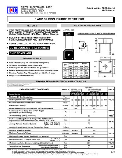
The Diotec 8 Amp Silicon Bridge Rectifiers are presented with key features such as void‑free vacuum die soldering, built‑in stress‑relief mechanisms and UL‑recognized construction. Mechanical specifications list a molded epoxy case, silver‑plated copper terminals and dimensions for various mounting options.
Electrical characteristics cover maximum ratings at 25 °C, including surge overload up to 400 A peak, DC blocking voltage of 400 V, forward voltage of 0.95 V at 4 A, and thermal resistance values. Characteristic curves illustrate forward current derating, surge capability and junction capacitance across temperature ranges.
| Surge Overload Rating | 400 A peak |
|---|---|
| Maximum Peak Reverse Voltage (VRWM) | 400 V |
| Maximum Forward Voltage at 4 A DC (VFM) | 0.95 V (typ. 0.90 V) |
| Continuous Power Dissipation @ 80 °C | 2 W |
| Junction‑to‑Ambient Thermal Resistance (RθJA) | 12 °C/W |
| Junction‑to‑Case Thermal Resistance (RθJC) | 5 °C/W |
The case is molded epoxy with a UL flammability rating of 94V‑0.
Yes, the rectifiers are RoHS compliant.
Soldering should follow MIL‑STD 202 Method 208, which is guaranteed.